Monday 20 April 2015

FRAMED!

As most users are aware, AutoCAD can insert more than just DWG content into a drawing: images, DWFs, PDFs, even Microstation files can all be attached via the XREF Manager.  These objects behave and look like DWG xrefs with one exception: they have borders, which in AutoCAD-speak is a "Frame".  

Every type of Frame has an assigned value, either 0, 1 or 2.  

A value of "0" means the frame is not visible (so the object cannot be selected), and the frame does not plot.

In order to select an attached image, PDF, DWF, or DGN file, the object frame must be visible, so a setting of "0" may not be ideal.

A value of "1" means the frame is visible (so the object can be selected), and the frame plots.


Here is a comparative look at the difference between visible and invisible frames around images.


What if you want to see the frame, but not have the frame plot? A value of "2" makes the frame visible (so you can select it), but does not plot it, which is great if you have overlapping imagery.  

Here is a simple cheat sheet to help remember what each setting does.

Each Frame type has its own setting (0, 1, 2), and can be for each specific AutoCAD variable:

Images:             IMAGEFRAME
PDFs:                PDFFRAME
DWFs:               DWFFRAME
DGN:                 DGNFRAME
Clipped XREF:   XCLIPFRAME
Wipeouts:          WIPEOUTFRAME


That's a lot of Frames to keep track of, but there also a handy way to control them all: the AutoCAD variable FRAME, which allows these 6 variables listed to be set at either 0, 1, or 2, or a FRAMES setting of 3 will let each individual object with frames use their own setting.


But wait! there's more, you can also control the display of frames for both OLE objects and point clouds!

OLE objects:    OLEFRAME
Point clouds:    POINTCLOUDCLIPFRAME

Both of these use the same 0, 1, 2 options as the rest of the Frames listed, but are not affected by FRAME settings.

There you have it: 8 AutoCAD Frame variables (6 which are controlled by 1 variable), and their settings

What's your preference? Are you a 0? Perhaps a 1?  Maybe you like the best of both worlds, and are a 2?  Share your thoughts!


Tuesday 14 April 2015

SETBYLAYER: Quickly change all object properties to ByLayer


Too often, we find anomalies in our drawings that can cause us tons of grief.  A particular nuisance is dealing with drawing objects with linetype and color properties not ByLayer.  

While MATCHPROP will fix some objects, it cannot correct blocks with hard-coded color and line types.

There is a powerful AutoCAD command that allows us to modify object properties: SETBYLAYER.

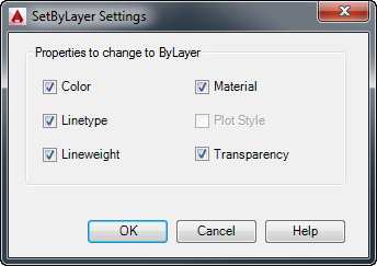
SETBYLAYER allows us to change overrides for color, linetype, lineweight, material, and plot style to ByLayer.  It even works for objects inside blocks!  The command is located in the MODIFY Panel, Home Tab of the AutoCAD Ribbon.


SETBYLAYER has a settings box where you assign which object properties are set to ByLayer.  You can access it by  typing S (or clicking Settings) at the command prompt after invoking the command.  AutoCAD also saves and lists current settings at the command prompt.


Once you have set which properties you want applied, you select the objects you want to have modified.  You can use any normal selection method here.

You will then be asked two questions:

Change ByBlock to ByLayer? [Yes/No]  :

and

Include Blocks? [Yes/No]  :


After the prompts, AutoCAD will run the command and report how many objects were modified, and how many of the selection set that were not changed.

SETBYLAYER also can change object color in a block from ByBlock to ByLayer, too!