Monday 23 February 2015

TEXTual Healing


Just about every AutoCAD document has text objects in it.  AutoCAD has a built in text editor (and a built-in mtext editor) with lots of power and functionality.  Here is a quick look at MTEXT and what we can do with it in the AutoCAD environment.

AutoCAD and MTEXT
The major annotation type is multi line text, called MTEXT.  Of course, you can create "text" in AutoCAD by other means: single line text (DTEXT), attribute text, dimension text, table text and hypertext. 


The real power with MTEXT is the ability to have multiple lines of text with word processor formatting all built inside of AutoCAD.


MTEXT: Friend or Foe?
Paragraph formatting is a powerful feature of MTEXT.  Right-click on the ruler of an MTEXT box  and the option to enter the Paragraph dialog appears (or click the Paragraph icon in the Text Formatting dialog).  Here, we can define tabs and indents for our text, a great way to organize numbered notes, for example.

Here is a more detailed explanation of the paragraph dialog, on Autodesk Exchange.

In my experience, a good place to start is to set left tab and hanging indent at 6.00 (for metric users), but as you can see, there is a lot more than simple indenting available.


Take a look at the decimal tab, for example; decimal tabbing is a pretty useful item for lining up numeric text.

With the Decimal tab  active, and a value of 10 added, selecting and tabbing mtext will line up the text with the decimals all justified, a handy way to organize numeric content!


The Columns Advance
Another powerful feature in MTEXT is column control.  MTEXT allows dynamic columns, which means the columns can be grip edited, or static columns where you define the number of columns and AutoCAD arranges the text.

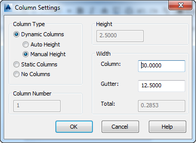
Settings to control column and gutter (the space between columns) width and more, depending on the column type selected, are all in the Column Settings dialog, accessed from the Text Formatting tool.


Power Tips
How can you get the neat little m2 to appear in MTEXT?  To make text superscript in MTEXT, type the m2, and then type the ^ caret symbol [shift + 6] next to it like so: m2^.  Select the 2 and the caret, right-click, and select Stack from the pop up menu.  That's it! You now have superscript text!  If you put the ^ in front of the text and stack them, AutoCAD will make it a subscript, so keep an eye on your carets, folks!

Every annotation in your drawing can be spell checked.  The command SPELL will search your drawing and compare the text to your assigned dictionaries.  There is hardly any excuse to have typos in AutoCAD these days.

Looking for text in all the wrong places?  Try the FIND command to see if the text exists in your drawing, and click Zoom to Highlighted Result and AutoCAD will display it.  I find it a handy way to find ASCM points in survey data files!

Line up your text quickly by selecting the separate elements and set the position X value in the properties palette to the same value: Voila! Your text is lined up!

Tuesday 17 February 2015

Overriding VP color in AutoCAD


Layers have been long capable of VPFREEZE, which makes all of the contents of a layer frozen in a particular viewport. Layers are of course, also capable of controlling an objects color: as long as an object is color is BYLAYER, then the color of the layer controls the colour of the object.  

Up to rather recently, there was no direct method to manage layer colour unique to each viewport.  Now there is a very cool blending of both features: VP Color.  With this feature, the color of layers can be set independently for every viewport.  One possible use is having a key plan that can show the same content as your drawing, but with faded colors.   


Layers that have overrides set in them display with a light blue background color, making them easy to identify.  (FYI VP overrides can also be assigned to linetypes, lineweights, and plot styles; these would have blue highlighting in any overrides, too.)

This is what the layer palette looks like with color overrides: we see affected layers highlighted, and the overridden colors displayed in the VP color column.  For simplicity of viewing, I placed the columns near one another.


To remove a VP override, right-click in the layer palette and select Remove Viewport Overrides for in the popup menu. AutoCAD offers options to remove overrides of selected layers, or overrides of properties, or even overrides for specific viewports, or removal of all overrides in all viewports.   


Lots of choice, lots of power.  

The best part of VP overrides is that there is no longer the need to copy objects to other layers so it can appear differently in every viewport!

Monday 9 February 2015

OSNAP: A closer look


A critical feature of AutoCAD is the accuracy in creating geometry.  A fast, simple way to achieve this is through Object Snaps, also called OSNAPS. Let's take a closer look.

AutoCAD is a SNAP
OSNAPs are a way to determine (or attach) to geometric locations or situations of objects in a drawing file. Different object types have different object snaps: a line has two ENDpoints and a MIDpoint, a circle has a CENter and 4 QUAdrants (think of them as north, south, east and west markers), an arc has a CENter, MIDpoint, two ENDpoints, and possibly QUAdrants, depending on the size.  Points have one object snap, the NODe.  Blocks and text have INSertion osnaps.

More OSNAPs!
INTersection, where any two objects cross
APParent intersection, when objects appear to cross, but are at different elevations
EXTension, which extends from the point selected, in the object’s direction
PERpendicular, forming a 90 degree angle to the selected object
NEArest, snaps to the nearest location, and
PARallel, where you create objects and select the object to run parallel with

All of these are called running object snaps, since they can be turned on (F3) and be running whenever AutoCAD prompts for geometric input.  There are a still few more:

FROm, you define a start location, and a displacement from it
M2P, midpoint between any 2 selected points
Point filters (.X, .Y, .Z, .XY, .XZ, .YZ) you acquire the selected positions from the geometry, and enter the remaining data (for example, you issue a command and type .XY: you snap to an object, and AutoCAD acquires the X and Y positions from the snap, and prompts for the Z, which you input.

How does it work?
For OSNAPs to work, they need to be running and on, or specified for a particular instance.  The object also needs to be within the APERTURE box of your crosshairs.  You can also tell when OSNAPs are running, by checking the OSNAP button in the status bar being highlighted. 

Running OSNAPs can be turned on from the OSNAP dialog; type OSNAP or OS at the command prompt.  You can also right click the OSNAP button on the status bar and select which osnaps you want to be running.

To make sure the aperture box is visible, set your APBOX variable to 1. Aperture size is set by APERTURE variable (7-8 is a good value).

You can also type the first 3 letters of the OSNAP name to activate a particular snap, or shift + right click to get the popup osnap menu.

AutoCAD remembers the OSNAPS you have turned on, and stores it as a number.  This number is unique for every setting, and is saved in the variable OSMODE.  In the graphic at the top, the OSMODE value for those shown (END, CEN, NOD, INT, INS, is 109.


AutoCAD can display a small marker and textbox describing the current osnap.  It can also set AutoCAD to “jump” to an osnap.  This is all accessed from the OPTIONS>Drafting Tab.

Osnaps can be initiated while within a command, just type ‘OS, and the osnap dialog will appear; set your running osnaps and exit back to the command!


A bit of advice
It is not recommended to have running osnaps for NEArest, TANgent, or PERpendicular, since these osnaps can be acquired whenever any part of the object is in the aperture box.  Probably best to only use these as overrides, else you get unexpected results!

Monday 2 February 2015

ARRAY of Sunshine

AutoCAD has for a long time, had a powerful modify command: ARRAY. ARRAY is essentially a multiple copy command, creating clones of a selection set on either a grid (rectangular) or circle (polar) arrangement. Since AutoCAD 2013, however, the ARRAY command has become even more versatile and powerful. Let's briefly look at both ARRAY commands: ARRAY and ARRAYCLASSIC.


ARRAYCLASSIC
This is the new name for the long standing command that prior to AutoCAD 2013 was simply called ARRAY. It creates multiple copies of a selection in either a rectangular or circular arrangement. The end result is a series of separate objects, all identical to the source selection.

Rectangular array prompts users for the number of rows, number of columns and the spacing between rows and spacing between columns. Polar array copies objects around a center point. Two of three criteria are required: number of objects, total angle to fill and angle between objects.

ARRAYCLASSIC gives the traditional dialog box, with plenty of user entry options, and even an in-window preview.


ARRAY
This is the new revamped command, with an old name. Much like its historic namesake, it creates multiple copies of a selection in a rectangular or radial pattern, but also along a path.  The big difference here is the array becomes its own object and is associative; the array can be selected and modified after creation!

Another major difference is the lack of a dialog box; the ARRAY command is driven at the command line. Here is a peek at the many options available when creating a path array:


As you can see there are powerful options inside of this command, perhaps more than a dialog box can support. Once an array is created or selected, a context-sensitive ribbon appears so the array parameters can be modified in the ribbon.


The new ARRAY command is very powerful, editable, and associative! Check it out!