Monday, 20 April 2015

FRAMED!

As most users are aware, AutoCAD can insert more than just DWG content into a drawing: images, DWFs, PDFs, even Microstation files can all be attached via the XREF Manager.  These objects behave and look like DWG xrefs with one exception: they have borders, which in AutoCAD-speak is a "Frame".  

Every type of Frame has an assigned value, either 0, 1 or 2.  

A value of "0" means the frame is not visible (so the object cannot be selected), and the frame does not plot.

In order to select an attached image, PDF, DWF, or DGN file, the object frame must be visible, so a setting of "0" may not be ideal.

A value of "1" means the frame is visible (so the object can be selected), and the frame plots.


Here is a comparative look at the difference between visible and invisible frames around images.


What if you want to see the frame, but not have the frame plot? A value of "2" makes the frame visible (so you can select it), but does not plot it, which is great if you have overlapping imagery.  

Here is a simple cheat sheet to help remember what each setting does.

Each Frame type has its own setting (0, 1, 2), and can be for each specific AutoCAD variable:

Images:             IMAGEFRAME
PDFs:                PDFFRAME
DWFs:               DWFFRAME
DGN:                 DGNFRAME
Clipped XREF:   XCLIPFRAME
Wipeouts:          WIPEOUTFRAME


That's a lot of Frames to keep track of, but there also a handy way to control them all: the AutoCAD variable FRAME, which allows these 6 variables listed to be set at either 0, 1, or 2, or a FRAMES setting of 3 will let each individual object with frames use their own setting.


But wait! there's more, you can also control the display of frames for both OLE objects and point clouds!

OLE objects:    OLEFRAME
Point clouds:    POINTCLOUDCLIPFRAME

Both of these use the same 0, 1, 2 options as the rest of the Frames listed, but are not affected by FRAME settings.

There you have it: 8 AutoCAD Frame variables (6 which are controlled by 1 variable), and their settings. 

What's your preference? Are you a 0? Perhaps a 1?  Maybe you like the best of both worlds, and are a 2?  Share your thoughts!


Tuesday, 14 April 2015

SETBYLAYER: Quickly change all object properties to ByLayer


Too often, we find anomalies in our drawings that can cause us tons of grief.  A particular nuisance is dealing with drawing objects with linetype and color properties not ByLayer.  

While MATCHPROP will fix some objects, it cannot correct blocks with hard-coded color and line types.

There is a powerful AutoCAD command that allows us to modify object properties: SETBYLAYER.

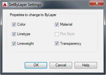
SETBYLAYER allows us to change overrides for color, linetype, lineweight, material, and plot style to ByLayer.  It even works for objects inside blocks!  The command is located in the MODIFY Panel, Home Tab of the AutoCAD Ribbon.


SETBYLAYER has a settings box where you assign which object properties are set to ByLayer.  You can access it by  typing S (or clicking Settings) at the command prompt after invoking the command.  AutoCAD also saves and lists current settings at the command prompt.


Once you have set which properties you want applied, you select the objects you want to have modified.  You can use any normal selection method here.

You will then be asked two questions:

Change ByBlock to ByLayer? [Yes/No]  :

and

Include Blocks? [Yes/No]  :


After the prompts, AutoCAD will run the command and report how many objects were modified, and how many of the selection set that were not changed.

SETBYLAYER also can change object color in a block from ByBlock to ByLayer, too!


Tuesday, 3 March 2015

AutoCAD: Using Fields to display VP Scale


At times despite our most diligent efforts, we inadvertently change the VP scale of a viewport, and end up with a plot that has an incorrect viewport scale.  With all of the tools available, there surely is a way to have AutoCAD display the viewport scale dynamically. Advanced users with programming expertise could do this programmatically using LISP and reactors, but there is also a much simpler solution: AutoCAD fields.  Here is a  great way to dynamically display your VP scale, using fields in mtext.

A field is a text representation of a specific object property or value of a drawing or system variable. Fields appear as normal text when plotted, but have a grey background onscreen, like this. The big difference between text and fields is a field will update if the element it references is changed. 


Some examples of field variables are: drawing name, login name, date, time, layout name. Fields can also display object properties such as object name, layer, color, linetype, and specific properties such as block name for blocks, center point of circles and arcs, or area of a polyline, or SCALE OF A VIEWPORT!

For this you will first need a viewport in your layout to assign the mtext field.  The next step is to create an mtext object, a good location is in one of the corners, perhaps lower left or lower right, either inside or outside. You can create some descriptive text as well, like "VIEWPORT SCALE ", and in the mtext editor right-click and select Insert Field... from the context menu; the Field dialog will appear. 


In the Field dialog, select the following
(as shown in the graphics):

Field category: Objects,
Field names: Object,
Object  type: Viewport, (to acquire the viewport, click the select objects icon to the top right of the Object Type area, and then select the viewport object
Property: Custom scale,
Format: Use scale name.  


AutoCAD will display the annotation scale (if applied) or the value of the VPSCALE variable. 


Since fields are dynamic, the dynamic scale will refresh with every open, save, plot, etransmit or regen (If this is not happening, set FIELDEVAL to 31).  If you wish to see it but not print it, place the mtext field on a non-plotting layer.  There you have it: a dynamic VPSCALE display!
 

Monday, 23 February 2015

TEXTual Healing


Just about every AutoCAD document has text objects in it.  AutoCAD has a built in text editor (and a built-in mtext editor) with lots of power and functionality.  Here is a quick look at MTEXT and what we can do with it in the AutoCAD environment.

AutoCAD and MTEXT
The major annotation type is multi line text, called MTEXT.  Of course, you can create "text" in AutoCAD by other means: single line text (DTEXT), attribute text, dimension text, table text and hypertext. 


The real power with MTEXT is the ability to have multiple lines of text with word processor formatting all built inside of AutoCAD.


MTEXT: Friend or Foe?
Paragraph formatting is a powerful feature of MTEXT.  Right-click on the ruler of an MTEXT box  and the option to enter the Paragraph dialog appears (or click the Paragraph icon in the Text Formatting dialog).  Here, we can define tabs and indents for our text, a great way to organize numbered notes, for example.

Here is a more detailed explanation of the paragraph dialog, on Autodesk Exchange.

In my experience, a good place to start is to set left tab and hanging indent at 6.00 (for metric users), but as you can see, there is a lot more than simple indenting available.


Take a look at the decimal tab, for example; decimal tabbing is a pretty useful item for lining up numeric text.

With the Decimal tab  active, and a value of 10 added, selecting and tabbing mtext will line up the text with the decimals all justified, a handy way to organize numeric content!


The Columns Advance
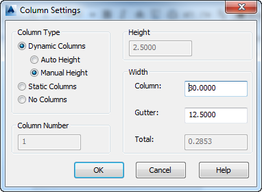
Another powerful feature in MTEXT is column control.  MTEXT allows dynamic columns, which means the columns can be grip edited, or static columns where you define the number of columns and AutoCAD arranges the text.

Settings to control column and gutter (the space between columns) width and more, depending on the column type selected, are all in the Column Settings dialog, accessed from the Text Formatting tool.


Power Tips
How can you get the neat little m2 to appear in MTEXT?  To make text superscript in MTEXT, type the m2, and then type the ^ caret symbol [shift + 6] next to it like so: m2^.  Select the 2 and the caret, right-click, and select Stack from the pop up menu.  That's it! You now have superscript text!  If you put the ^ in front of the text and stack them, AutoCAD will make it a subscript, so keep an eye on your carets, folks!

Every annotation in your drawing can be spell checked.  The command SPELL will search your drawing and compare the text to your assigned dictionaries.  There is hardly any excuse to have typos in AutoCAD these days.

Looking for text in all the wrong places?  Try the FIND command to see if the text exists in your drawing, and click Zoom to Highlighted Result and AutoCAD will display it.  I find it a handy way to find ASCM points in survey data files!

Line up your text quickly by selecting the separate elements and set the position X value in the properties palette to the same value: Voila! Your text is lined up!