Showing posts with label Blog. Show all posts

Monday, 23 September 2019

Power Tip: Selection Cycling

Today's Power Tip is for those who frequently use modify commands, which may be everyone!

Object selection is one of the most common operations for all AutoCAD users.  In fact, one of the most valuable assets of AutoCAD is the ability to re-use existing information.  Every modify command in AutoCAD prompts the user to select objects:


Selection Methods
Previously, we covered Window, Crossing, and FASTSEL selection options. These are each their own selection tool, and can be invoked individually.  However, there is yet another way to invoke these selection options: Selection Cycling.


What is Selection Cycling?
Selection Cycling is available when using pick and drag lasso. After press and holding the left mouse button, if the user moves the cursor to the right, the standard window selection (as noted by the blue background and solid border) begins, if the drag begins to the left, the standard crossing selection (as noted by the green background and dashed border) begins.


How do I access it? 
You can press the space bar during the press-drag to CYCLE through selection modes: Pressing the space bar cycles the selection modes: Crossing, Window, and Fence! The dragged path of the mouse forms the fenceline; AutoCAD automatically closes the boundary to form the window (or crossing) polygon.


Selection cycling allows AutoCAD users to quickly and easily control object selection, giving 3 great selection options all inside one operation!


 What's your favourite selection tool?  Share your thoughts in the Comments section.


Monday, 29 June 2015

eTRANSMIT on All Frequencies, All Languages


Sending AutoCAD data is more complicated these days, since a dwg file can be connected to other drawings, images, PDF files, spreadsheets, and can contain custom fonts, linetypes, and hatches. Sending a dwg file on its own can leave the end user missing important information that may be contained in external locations.  When someone requests a "CAD file", users need to be diligent that the recipient gets the drawing and all dependencies related to it.  AutoCAD has a command that does this: ETRANSMIT.

Why should I use this?
ETRANSMIT is a powerful command; it gathers a list of all external elements (files, images, spreadsheets, PDFs, materials, CTBs, STBs, etc) and allows users to compile them into a folder or zip file.  It allows users to ensure a drawing file has all of its dependencies included when sending an AutoCAD drawing. ETRANSMIT also creates a text file listing the documents in the transmittal.


How does it work?
The command opens a dialog box displaying a list and table tab of every drawing dependency. Next to every item is a check box for selection of included elements; only checked items are included when the transmittal is created.  Users can fine tune each and every component included. You must save first, since ETRANSMIT can only be invoked immediately after a save is performed. 


OK, what happens after that?
Once the contents are determined, users select the transmittal setup, which can be saved with a custom name.  The transmittal setup determines several settings:

  •  Package type (Zip, exe, or set of files)
  •  File format (2000, 2004, 2007, 2010)
  •  Transmittal save location
  •  Pathing options (organized, single folder, or as-is)
  • Other options, such as password protection, XREF binding, and fonts/materials inclusion

On the bottom of the Modify Transmittal Setup dialog is a description area, where you can name your setup.  This is the name that appears in the transmittal setup description.

So many choices!
With so many options, here are a few tips:
  • Use Zip as the package type: just one file to deal with, and the *.exe file may get stopped by firewalls or email filters. 
  • Keep the file format as current as you and your destination's versions allow.
  • Uncheck Materials, unless you definitely use them in the drawing files.
  • Include fonts, since different versions of AutoCAD use different .SHX libraries.
  • Give your setup an intuitive name (Zip - No folder structure preserved, etc.)
There's plenty more features available, too, such as password protecting your transmittal, or binding XREFs.  

Comment and share your settings/tips!

Monday, 26 January 2015

Staying on Track


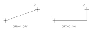
Most regular AutoCAD users will know that the F8 key toggles the ORTHO mode, which constrains cursor movement horizontal and vertical to the current UCS. There are also 2 types of tracking we can use to allow us to draw quickly and accurately, object snap tracking and polar tracking.  POLAR, ORTHO, OSNAP, and OTRACK are all selectable toggles in the status bar, normally found at the bottom of the AutoCAD environment.


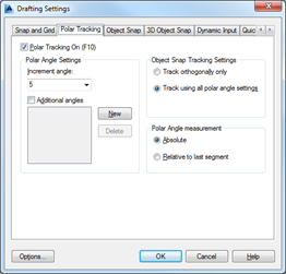
OTRACK allows tracking along alignment paths based on other OSNAP points.  F11 switches it on and off. When active, OSNAP tracking allows you to project from an acquired OSNAP, the cursor follows along a dotted line that represents the ortho extension. By default, the tracking is orthogonal only; it can be modified on the Polar Tracking tab of drafting settings, DSETTINGS. Note: for OTRACK to work, there need to be running OSNAPS on (AUTOSNAP).

POLAR tracking allows tracking along any defined polar angle tracking path from any point, no OSNAP is required. F10 switches it on and off. The angles evaluated for the POLAR is defined in the Drafting Settings, Polar Tracking Dialog box, too.  Both settings' state is visible on the status bar at the bottom of the AutoCAD main window.


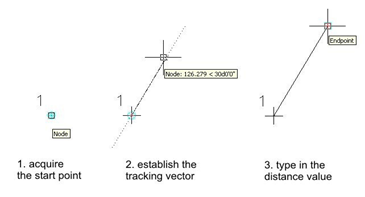
As an example, let’s draw a line at an angle of 30 degrees from a selected start point at a length of 200 units.

First, turn POLAR on (F10), and set the increment angle to 30 or to a divisor of 30 (5, 10, 15) in the Polar Tracking tab. Now, start the LINE command, and select your start point. As you drag your cursor alone paths that are along the angular increments, the POLAR tracking vector will appear. Once that is highlighted, you can simply type in the distance value (200) and AutoCAD will draw the line at the specified length along the POLAR tracking angle selected.


Here is a second example, drawing a line from a known point to a point orthogonal  to two existing corner points.  First start the LINE command, and OSNAP the upper right intersection of the lower object.


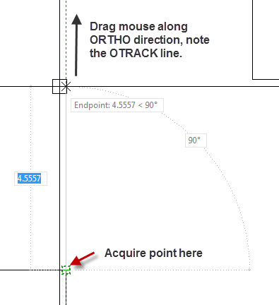
With ORTHO and OTRACK on, drag your mouse vertically, you should see a faint green dashed line representing the ortho extension from your selected point stretching upwards.  This symbol means the otrack has established the vertical lORTHO from the corner as a potential OTRACK.  Next, hover your crosshairs on the second object corner, but do not left-click! We are simply using the corner to establish the OTRACK line.  Instead, drag your crosshairs horizontally; you should see the faint green dashed line extend horizontally as you move.  


When you get to the point where the vertical and horizontal extensions meet, both green dashed lines appear, as shown in the image to the right.  Click when both green dashed lines appear, now, and the line endpoint will be at the projected extensions intersection.

That's a simple example of how OTRACK can help you acquire locations or situations with no geometry in the desired location.  Of course, there are lots of other possibilities, too.

Feel free to share your POLAR and OTRACK usage experiences!


Sunday, 14 December 2014

Welcome to Frozen Layers!

Edmonton January: Blue sky, white everything else.
Being Canadian has both benefits and challenges.  For example, we have free health care, hockey, and poutine.  There may be more benefits besides those to being Canadian, but I think I've covered the important bits already!

There is a slight downside to Canada-winter: those 3 or 4 (or more!) months when you only see your neighbour when you're both shoveling the driveway clear of the overnight snowfall, or perhaps pushing his car when he is stuck at the end of the street.  I know, soon enough, it will be April, and folks will start venturing outside once again.  Barbecues will be uncovered, the snow brushes get put away (till that big storm in May), and thoughts turn to the garden once again.  It isn't all bad, really: having bad weather helps appreciate the good weather even more.

The weather doesn't inhibit my love of AutoCAD, though, and I figure after a couple years writing on internal blogs, it's high time to share publicly tips, solutions, and news about AutoCAD.  So, here we go! 

After noting that every cool (and every awful) CAD pun has long since been used, I chose Frozen Layers, since it is not only a part of AutoCAD, but a part of being Canadian.  Since I find it beneficial when understand how things work, I'll try to explain things here best I can.

Time to grab a double-double!